
-
"NetSkateKoban" / "NetSkateKoban Nano" are registered trademark of Cyber Solutions Inc.
-
All brand or product names are trademarks or registered trademarks of their owners.
Login
Login
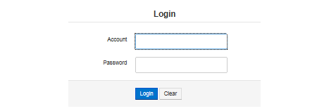
This is the first screen that is displayed on connecting to Nano.
Enter your Account and Password, and click Login.
Initial settings are given below.
Account |
admin |
Password |
NetSkateKoban |
|
You must change your password from the above default password. For information on how to change password click here. |
Related operations
Safe Mode
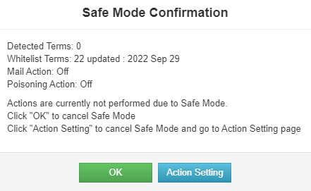
Safe Mode is the mode from Nano reboot to first login. During this time, actions such as Mail notification, Blocking or Auto Registration are not performed.
In this mode, the Safe Mode Confirmation dialog is displayed at the center of the screen. Following information is displayed on this dialog, as currently set in Nano.
-
Detected Terms: Number of Detected Terminals
-
ATL Terms: Number of Terminals Registered in ATL
-
Mail Action setting
-
Blocking Action setting
[About Safe Mode Confirmation dialog]
Click "OK" or "Action Setting" in the Safe Mode Confirmation dialog box to cancel Safe Mode.
At this point, to change the action settings, such as to stop poisoning, click "Action Setting" and change the settings on the Action Setting screen.
Click "OK" to go to Detected Terminal List.
|
To connect to other network without changing the ATL, remove from the network and change the settings in a standalone state connected to the hub. |
Related operations
Terminal List
Detected Terminal List
Detected Terminal List gives the list of terminals connected to the network.
The terminal here refers to any device (PC, console, smart phone etc.) connected to the network.
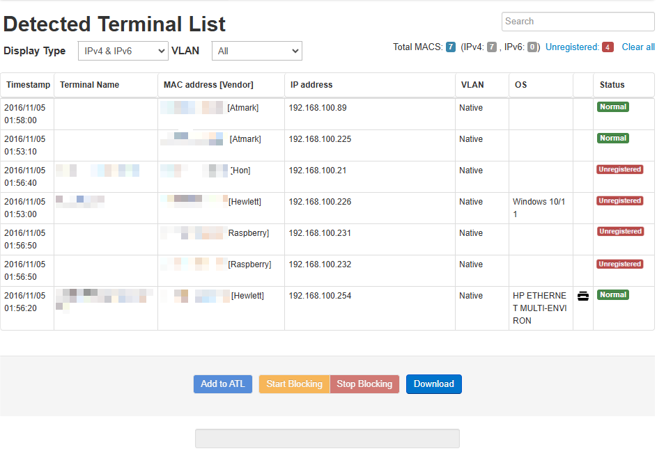
Detected Terminal List has the following items. The list can be sorted by left-clicking the header part with the mouse.
| Item | Description | |||||||||||||||||||||||
|---|---|---|---|---|---|---|---|---|---|---|---|---|---|---|---|---|---|---|---|---|---|---|---|---|
Timestamp |
Displays the time when the terminal was detected. |
|||||||||||||||||||||||
Terminal Name |
1. If "Terminal Name" is set in "ATL Settings" → "Edit", the registered terminal name will be displayed. |
|||||||||||||||||||||||
MAC address [Vendor] |
Displays the MAC address of the terminal in the following format. Format : MAC address [Vendor] For randomized MAC addresses, if the vendor information could be determined, it would be [local.vendor name], |
|||||||||||||||||||||||
IP address |
Displays terminal’s IP address. |
|||||||||||||||||||||||
VLAN |
The VLAN ID of the VLAN to which the terminal is connected is displayed.[Note] The Native VLAN will be displayed as native. |
|||||||||||||||||||||||
OS |
Displays OS name of the terminal. Since the OS name is inferred from the packet information etc. of the terminal, it may not always match the actual OS name. |
|||||||||||||||||||||||
Device Type |
Displays detected device types as icons. "L2L3Dev" refers to a device that has both L2 and L3 capabilities.
|
|||||||||||||||||||||||
Status |
Displays the status of the terminal. Status is "Normal" if the terminal is registered in ATL,"Unregistered" if the terminal is not registered in ATL and "Blocking" if an unregistered terminal is being blocked. |
|
Note
Functions related to VLAN are exclusively for Nano(V). |
Related operations
View the connected terminals
When Nano is monitoring the network, the connected terminals can be confirmed by opening this Web screen.
-
Open Detected Terminal List
After logging in, click on the top menu "Terminal List" > "Detected Terminal List". List of terminals that are connected to the network is displayed.
-
Select Display Type
By selecting Display Type "IPv4", "IPv6" you can display only IPv4 address and IPv6 address in the list respectively.
-
Select Display VLAN
By selecting the VLAN ID in Display VLAN, the terminals connected to only the corresponding VLAN can be displayed in the list. [Note]
|
Note
Functions related to VLAN are exclusive to Nano(V). |
Search Detected Terminals
Search for the detected terminals from the Detected Terminal List (Web screen).
-
Open Detected Terminal List.
Click on "Terminal List" > "Detected Terminal List" in the top menu.
-
Enter Search text.
Enter the character string to be searched in the search box at the top right of the Detected Terminal List (Web screen).
-
Check the Search results.
Terminals matching the search criteria will be displayed in the Detected Terminal List.
Register Detected Terminals
Add unregistered terminals to ATL from Detected Terminal List (Web screen).
-
Open Detected Terminal List.
Click on the "Terminal List" > "Detected Terminal List" in the top menu.
-
Select the terminal from the list
Select the terminal to be registered from "Detected Terminal List". Select multiple terminals by Ctrl + left click.
-
Register to ATL
Click on "Add to ATL" at the bottom of the list.
-
Select registration information
Select information for ATL.
The registration information that can be selected for Non-VLAN-compatible Nano is given below.
| Item | Description |
|---|---|
Register only MAC address |
Register only the MAC address of the corresponding terminal. |
Register MAC address and IP address |
Register the MAC address and IP address of the corresponding terminal. |
The registration information that can be selected for VLAN-compatible Nano(V) is given below.
| Item | Description |
|---|---|
Register only MAC address (permit connection to VLAN during detection) |
Register the MAC address of the relevant terminal and the VLAN ID of the connected VLAN. |
Register only MAC address (permit connection to all VLANs) |
Register the MAC address of the corresponding terminal. Applicable terminals can be connected to all VLANs. |
MAC address/IP address registration (permit connection to VLAN during detection) |
Register the MAC address and IP address of the corresponding terminal and the VLAN ID of the connected VLAN. |
MAC address/IP address registration (permit connection to all VLANs) |
Register the MAC address and IP address of the corresponding terminal. Applicable terminals can be connected to all VLANs. |
|
If you register a terminal on the ATL using a combination of MAC address and IPv4 address, the IPv6 address used by the terminal with that MAC address and the IPv4 address assigned by APIPA will also be treated as registered, and their status will be determined as "Normal." |
Manual Blocking
Execute Blocking to Detected Terminals selected in Detected Terminal List (Web screen). Click on "Nano Management" → "Action Settings" and click on "Enable" at "Manual Blocking". For more information, please refer Action Settings.
-
Open Detected Terminal List.
Click on the "Terminal List" > "Detected Terminal List" in the top menu.
-
Select blocking targets
Select the terminal to block from "Detected Terminal List". Select multiple terminals by Ctrl + left click.
-
Start Blocking
Click on "Start Blocking" at the bottom of "Detected Terminal List".
-
Display Confirmation Dialog
The blocking explanation and the information of blocking targets are displayed.
Then you click OK, blocking is started.
This dialog is displayed when selected "Confirm before Blocking" in Action Settings. For more information, please refer Action Settings.
|
When using Normal Blocking, the number of simultaneous blocking processes is 25 each for IPv4 and IPv6 addresses. |
Stop Blocking
Blocking can be stopped for multiple terminals together from the Detected Terminal List (Web screen).
-
Open Detected Terminal List
Click on "Terminal List" > "Detected Terminal List" in the top menu.
-
Specify the Blocked terminal
Select multiple terminals for which Blocking needs to be stopped. Ctrl + Left click to select multiple. By clicking "Unregistered" at the upper right of the Detected Terminal List, all the Blocked terminals can be selected.
-
Stop Blocking (batch)
Click on "Stop Blocking" button at the bottom (in the center right) of the Detected Terminal List.
Download Detected Terminal List
Download the terminals displayed in the Detected Terminal List (web screen) in CSV format.
-
Open the Detected Terminal List.
Click on Terminal List > Detected Terminal List in the top menu.
-
Start download
Click on "Download" button below the Detected Terminal List to download the data as a CSV file.
|
The character encoding of the downloaded CSV file is SJIS. If you have changed the "Display Type" or "VLAN" filter, or used the search function, only the information shown on the screen will be downloaded. |
Blocked Terminal List
The Blocked Terminal List gives all the terminals which are blocked by Nano.
Blocked terminals cannot communicate normally. If the blocking has been done by mistake, it can be stopped from this list.
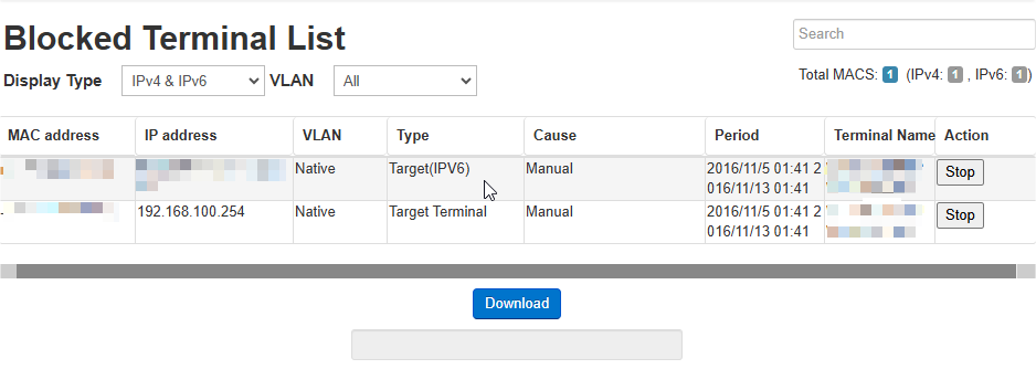
This screen has the following items.
The list can be sorted by left-clicking the header part with the mouse.
| Item | Description |
|---|---|
MAC address |
Displays the MAC address of the terminal being blocked. |
IP address |
Displays the IP address of the terminal being blocked. |
VLAN |
Displays the VLAN ID of the VLAN to which the terminal is connected.[Note] Native VLAN will be displayed as native. |
Type |
Displays the Type of blocking being done. |
Cause |
Displays the reason that caused blocking to be done. |
Period |
Displays the period for which the terminal will be blocked. |
Terminal Name |
Displays the terminal name. |
Action |
Click Stop in this column to stop blocking of the target terminal. |
Reasons for blocking terminal detection include.
| Blocking reason | Description |
|---|---|
Unregistered |
Blocking of terminals that are not registered in the ATL or that do not have a registered IP address. |
Violation of usable Period |
Blocking of terminals that are allowed listed but have mismatch in the time period. |
PC violation flag |
Blocking of terminals that are registered in the ATL but do not meet the conditions set by the Nano administrator. |
Manual |
Blocking of terminals that are executed with "Start Blocking" button on Detected Terminal List. |
In addition to the above, in case of blocking Syslog Linkage Or SNMP Trap Linkage, the name of each linked product will be displayed as the reason for blocking.
|
Note
Functions related to VLAN are exclusively forNano(V). |
Related operations
View Blocked Terminal List
The blocked terminals can be checked from the Blocked Terminal List (Web screen).
-
Open the Blocked Terminal List
Select from the top menu "Terminal List" > "Blocked Terminal List".
-
Select "Display Type" filter
By selecting "IPv4" or "IPv6" in the "Display Type" filter, you can display only IPv4 addresses or IPv6 addresses in the list, respectively.
-
Select "VLAN" filter
By selecting the VLAN ID in the "VLAN" filter, the terminals corresponding to each VLAN only can be displayed in the list. [Note]
|
Note
Functions related to VLAN are exclusively for Nano(V). |
Stop Blocking
Stop blocking from Blocked Terminal List (Web screen).
-
Open the Blocked Terminal List
Click on "Terminal List" > "Blocked Terminal List" in the top menu.
-
Stop Blocking
Click on "Stop" in the "Action" column to stop terminal blocking.
Search Blocked Terminals
Search for the blocked terminals from Blocked Terminal List (web screen).
-
Open Blocked Terminal List.
Click on Terminal List > Blocked Terminal List in the top menu.
-
Enter Search text.
Enter the character string to be searched in the search box at the top right of the Blocked Terminal List (web screen).
-
Check the search results.
Terminals matching the search criteria will be displayed in the Blocked Terminal List table.
Download Blocked Terminal List
Download the terminals displayed in the Blocked Terminal List (web screen) in CSV format.
-
Open a Blocked Terminal list.
Click on Terminal List > Blocked Terminal list in the top menu.
-
Start download
Click on "Download" button below the Blocked Terminal list to download the data as a CSV file.
|
The character encoding of the downloaded CSV file is SJIS. If you have changed the "Display Type" or "VLAN" filter, or used the search function, only the information shown on the screen will be downloaded. |
ATL Setting
View ATL
This screen shows the current ATL. It can be used for checking the ATL after editing.
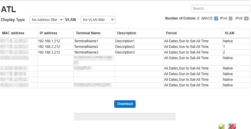
This screen has the following items.
The list can be sorted by left-clicking the header part with the mouse.
| Item | Description |
|---|---|
MAC address |
The MAC address of the terminal. |
IP address |
The IP address of the terminal. |
Terminal Name |
The terminal name that is set when it is registered. Displayed as the terminal name in the list of detected terminals. |
Description |
The description that is set when it is registered. |
Period |
The period during which the terminal can be connected. |
VLAN |
Displays the VLAN information (VLAN ID, etc.) to which the terminal is permitted to be connected.[Note] |
|
Note
Functions related to VLAN are exclusively forNano(V). |
Related Operations
Edit ATL
This screen can be used to register, modify, or delete terminals from the ATL used by Nano.
A terminal is specified by the combination of IP address and MAC address. To register a terminal, enter the IP address and MAC address.
Click on "Save" to save the ATL after editing.
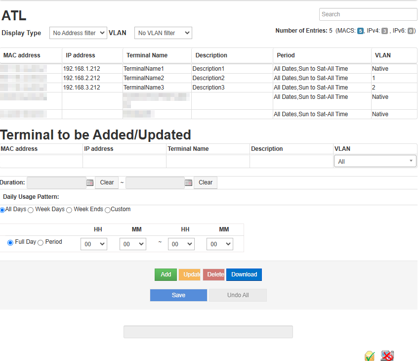
This screen has the following items.
The list can be sorted by left-clicking the header part with the mouse.
| Item | Description |
|---|---|
MAC address |
The MAC address of the terminal. Please specify separated with colon (:). |
IP address |
The IP address of the terminal. Specify IPv4 separated by dot(.) and IPv6 separated by colon(:). If the IP address is not specified, then the check whether the terminal is registered or not is done only with the MAC address, when the terminal is detected. |
Terminal Name |
Register the name of the terminal. Displayed in "Detected Terminal List". This is optional. |
Description |
Enter the description for the terminal. This is optional. |
VLAN |
You can specify the VLAN that allows connection of the terminal from the pull-down menu. |
Duration |
Specify the period (<From Date> to <To Date>) of time for which the terminal can be connected. If the duration is not set, then the terminal connection will not be limited by date. |
Daily Usage Pattern |
Specify the day of the week on which the terminal can be connected. On selecting the details, the time for each day of the week can be specified. |
Period |
Specify the time<Hour>:<Minutes>) to (<Hour>:<Minutes> when the terminal can be connected. If 00:00 to 00:00 is set, then the terminal connection will not be limited by time. |
|
Note
Functions related to VLAN are exclusively forNano(V). |
|
If you register a terminal on the ATL using a combination of MAC address and IPv4 address, the IPv6 address used by the terminal with that MAC address and the IPv4 address assigned by APIPA will also be treated as registered, and their status will be determined as "Normal." |
Related operations
Register a Terminal by entering it’s information
Register the terminal into ATL by entering the information using Edit ATL (Web screen).
-
Open the ATL Edit screen
Click on "ATL Setting" > "Edit" on top menu.
-
Enter the Terminal information
Enter the terminal information in "Terminal to be Added/Updated". In addition, you can also set the Period for which you want to allow the connection.
-
Add
Click on "Add" at the bottom of the "ATL" screen.
-
Save
Click on "Save" at the bottom of the "ATL" screen.
Filter Terminals in ATL
You can filter the registered terminals on the View ATL (Web Screen) and Edit ATL (Web Screen).
-
Open View ATL or Edit ATL.
Click on ATL Settings > View or Edit in the top menu.
-
Select "Display Type" filter.
Select "IPv4" or "IPv6" from the "Display Type" filter to show only IPv4 or IPv6 addresses in the list.
-
Select the "VLAN" filter.
Select a specific VLAN ID from the "VLAN" filter to display only the terminals connected to that VLAN in the list.[Note]
|
Note
Functions related to VLAN are exclusively forNano(V). |
Search Allowed Terminals
Search for the allowed terminals from View ATL (Web Screen) and Edit ATL (Web Screen).
-
Open View ATL or Edit ATL.
Click on ATL Settings > View or Edit ATL Settings in the top menu.
-
Enter Search text.
Enter the character string to be searched in the search box at the top right of the View ATL (Web screen) or Edit ATL (Web screen) screen.
-
Check the search results.
Terminals matching the search criteria will be displayed in the View ATL (Web screen) or Edit ATL (Web screen) table.
Download ATL
Download the terminals registered in the View ATL(Web screen) and Edit ATL(Web screen) in CSV format.
-
Open View ATL or Edit ATL.
Click on ATL Settings > View or Edit ATL Settings in the top menu.
-
Start download.
Click on "Download" button below the View or Edit ATL to download the data as a CSV file.
|
The character encoding of the downloaded CSV file is SJIS. If you have changed the "Display Type" or "VLAN" filter, or used the search function, only the information shown on the screen will be downloaded. |
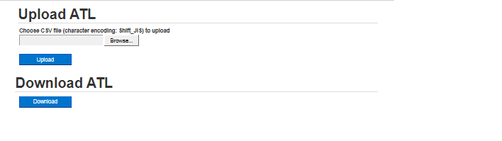
Upload/Download
With Upload of ATL, you can register the terminals collectively by uploading a ATL created in advance.
With ATL Download, you can download the current ATL.
|
The character coding of the downloaded CSV file is SJIS. The character coding of the CSV file to be uploaded should also be SJIS. If a CSV file set to any other character coding is uploaded, there is a possibility that the characters will be garbled. |
Related operations
Register a batch of terminals
Register terminals together as a batch by uploading a ATL prepared in advance.
-
Open the Upload screen of ATL
Click on "ATL Setting" > "Upload/Download" in the top menu.
-
Select the ATL
Click on Browse and select the file to upload.
-
Upload
Click on "Upload" after selecting the file.
Reports
Report List
From this screen, you can download a list of Detected Terminals, a list of Blocked Terminals, Allowed Terminals, and Weekly Usage Report as a CSV file.
In particular, the Weekly Usage Report saves the connection history of the terminal from Monday, and you can create a PDF report for one week by using a dedicated tool.
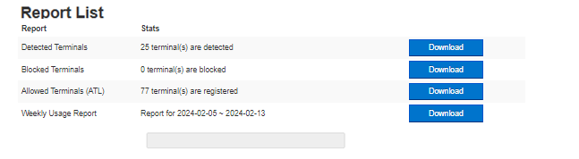
Download Reports
From this screen, you can download the following CSV files and tgz files.
| File | Description |
|---|---|
Detected Terminals |
List of currently detected terminals are saved in this file. |
Blocked Terminals |
List of blocked terminals are saved in this file. |
Allowed Terminals |
The current ATL is saved in this file. |
Weekly Usage Report |
Connection history for the week is saved in this file. The downloaded archive file will be a tgz format file. You can create a weekly report in PDF format by processing this file using the software called UsagePatternTool distributed separately. For more information on how to generate a weekly report click here. UsagePatternTool can be downloaded from NetSkateServiceCenter. |
[About NetSkate Service Center]
Access to the NetSkate Service Center requires a user account and password issued during user registration.
If you are unsure, contact the retailer from whom NetSkateKoban Nano was purchased.
|
The Blocked Terminal report cannot be downloaded, if there are no blocked terminals. Downloaded Weekly Usage Report can be used to create the report in PDF format. |
Related operations
Generate Weekly Reports
Generate PDF reports using weekly reports that can be downloaded from the Report List (Web screen).
-
Open Report List
Click on "Reports" in the top menu.
-
Download Weekly Report
Click on "Download" button of Weekly Usage Report.
-
Expand the downloaded tgz file
Unzip the downloaded tgz file. Expanding it twice will get you a folder containing weekly reports. Each folder contains a weekly report file for each VLAN.
-
Download UsagePatternTool
Generate Weekly Reports in PDF format. Login to NetSkateServiceCenter and download UsagePatternTool.zip.
[About NetSkateServiceCenter]
Access to the NetSkate Service Center requires a user account and password issued during user registration. If you are unsure, contact the retailer from whom NetSkateKoban Nano was purchased.
Java environment is required to execute UsagePatternTool. Please follow the steps below to install.
-
Access the following URL, and select your system from
Select a platform. -
Click on
Install JRE. The installer will be downloaded. -
Run the downloaded installer.
-
On the "Custom Setup" screen, select
Add to PATHPlease enable the option (enabled by default)
-
-
When installation is completed, Java environment preparation is complete.
-
-
Unzip UsagePatternTool
Unzip UsagePatternTool.zip using software that can unzip files in Zip format.
-
Move Weekly Reports
Move the Weekly Report downloaded in Step 2 or extracted in Step 3 to the "data\nano" folder in the UsagePatternTool folder.
-
Execute NanoUsagePatternTool.bat
Double-click "NanoUsagePatternTool.bat" in the UsagePatternTool folder.
-
Generating PDF reports
After running "NanoUsagePatternTool.bat", wait a little and a graph called Gantt chart will be displayed. Click on the PDF report output at the bottom right of that screen.
Select a folder and press OK to create the report.
Nano Setting/Network Setting
The Nano can be configured using this screen. For example, it is possible to set the password to open the web screen, the Nano timestamp and about obtaining log information for support etc.
Related Operations
-
Appliance
-
System Management
-
System Status
-
Network Configuration
-
Password
-
-
Koban Nano
-
Nano Status
-
Nano Configuration
-
Active Detection
-
IPv6 Active Detection
-
Monitoring VLAN setting
-
-
Linkage Setting
-
Syslog Linkage
-
SNMP Trap
-
-
System Management
Upgrade Nano Firmware
Upgrading the firmware version of Nano or applying a patch can be done from Nano setting (Web screen).
-
Open Nano Setting/Network Setting
Click on "Nano Management" > "Nano Setting/Network Setting" in the top menu.
-
Open the System Management screen
Click on System Management in the menu on the left side of the screen.
-
Open the Upgrade screen
Click on Upgrade of the Firmware Upgrade.
-
Specify the Upgrade file
Click on Browse for Firmware Upgrade, select a file for the upgrade.
-
Upgrade
Click on Upgrade of the Firmware Upgrade screen. Click OK in the confirmation dialog to start the Upgrade.
List of error messages
An error message will be displayed if the firmware update fails. The displayed error messages are given below.
| Error | Cause | Items to check * Solution |
|---|---|---|
Not a target type for update file |
The update file and Nano’s model number are different |
Apply the same update file as the Nano model number. |
Current installed VERSION is too old for the Patch. |
The applied update file does not correspond to the version of Nano |
Check the version number range in the update file name. |
Patch is broken. Firmware update is cancelled. |
The update file is corrupted |
The update file may not have been downloaded correctly. |
The package uploading was failed |
Applied files other than update files |
Please select the correct file for the update. |
Mounting of file system failed. |
Nano failed to change filesystem while running update |
Apply the update file again after restarting Nano. |
Extraction of Package from Patch failed. |
Nano failed to extract update files during update |
|
Execution of firmware update script failed. |
Nano failed to execute update script during update |
|
Unable to execute firmup.sh |
Nano failed to execute update script during update |
|
Firmware upgrade failed |
Firmware update failed for reasons other than the above |
|
Note1
For details about how to get the operation log, please refer here. |
Save current configuration of Nano
Backup current Nano Configuration file.
-
Open Nano Setting/Network Setting
Please click on the Top menu Nano Management > Nano Setting/Network Setting.
-
Open the System Management screen
Click on System Management in the menu on the left side of the screen.
-
Opens the Backup Management screen
Click on Backup under Backup Management.
-
Perform backup
Click on Backup to perform the backup. A file save dialog is displayed.
-
Save file
Specify a folder, and then save (Save as).
Restore saved Nano settings
Recover the backed up Nano settings.
-
Open Nano Setting/Network Setting
Click on "Nano Management" > "Nano Setting/Network Setting" in the top menu.
-
Open System Management screen
Click on System Management from the menu on the left side of the screen.
-
Open the Backup Management screen
Click on "Backup" of "Backup Management".
-
Specify the settings file and the ATL file to be restored
Click the first "Choose File" below Restore and specify a backup file of settings.
Also, click the second "Choose File" below Restore and specify the ATL file.
If no ATL file is specified, the current ATL setting will be used after restore.
If no record is registered in the current ATL and blocking is enabled in the backup file to be restored, then blocking will be performed to all terminals after restore.
If the situation happens, please initialize Nano to factory setting by hardware button.
-
Perform Recovery
Click on "Recovery" under the Partition Recovery. Restoring of the disk partition begins.
While performing Recovery, the terminal monitoring operation will stop until Nano is restarted. After the Recovery is completed, check the recovered disk partition and ATL information and restart Nano.
Full Backup
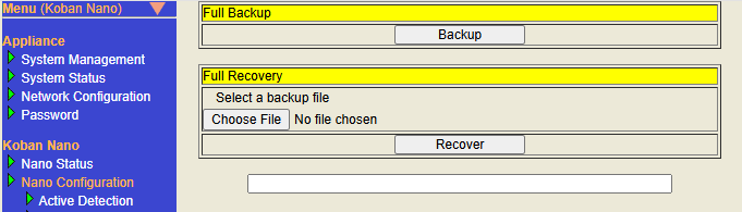
The full backup function is an extension of normal backup. In addition to the traditional backup information, full backup includes ATL information. Use this when you want to backup and recover Nano’s settings and ATL information at the same time.
Full backup procedure
-
To open Nano Setting/Network Setting
Click Nano Management > Nano Setting/Network Setting in the top menu.
-
To open the System Management screen
Click on System Management in the menu on the left side of the screen.
-
To open the Full Backup management screen
Click "Full Backup" in full backup and recovery management.
-
To run Backup
Click "Backup" to run a full backup. Full backup file download will start.
-
Download complete
Please save the full backup file that has been downloaded in any folder.
Full Recovery
Restore full backup Nano settings.
-
To open Nano Setting/Network Setting
Click Nano Management > Nano Setting/Network Setting in the top menu.
-
To open the System Management screen
Click on System Management in the menu on the left side of the screen.
-
To open the Full Backup management screen
Click "Full Backup" in full backup and recovery management.
-
To specify the configuration file to restore
Click "Browse…" or "Choose File" and specify the full configuration backup file.
-
To execute Full Recovery
Click "Recover" in Run Full Recovery. A dialog will appear. Click OK on dialog choices to start full recovery. Nano will automatically reboot after full recovery.
Restart Nano
Restart of Nano can be done, after changing the settings, from the Nano Settings (Web screen).
-
Open Nano Setting/Network Setting
Click on "Nano Management" > "Nano Setting/Network Setting" in the top menu.
-
Open the System Management screen
Click on "System Management" from the menu on the left side of the screen.
-
System Reboot
Click on Reboot for restarting the System. Click OK on the confirmation dialog to restart.
Nano Shutdown
To safely stop Nano, Shutdown the Nano from the Nano Settings (Web screen).
-
Open "Nano Setting/Network Setting"
Click on "Nano Management" > "Nano Setting/Network Setting" in the top menu.
-
Open the System Management screen
Click on System Management from the menu on the left side of the screen.
-
Shutting down the system
Click Shutdown for System Shutdown. Click OK in the confirmation dialog to start Shutdown.
Recover Nano Partition
If a file system failure occurs in the Nano working partition (where configuration files are stored), it can be rebuilt and recovered from the System Management screen.
-
Open "Nano Setting/Network Setting"
Click on "Nano Management" > "Nano Setting/Network Setting" in the top menu.
-
Open the System Management screen
Click on "System Management" from the menu on the left side of the screen.
-
Partition Recovery
Click on Recovery. Click OK in the confirmation dialog to start recovery.
Get the Operation Log of Nano
You can download the configuration and operations information of Nano as operations log from System Management screen.
-
Open Nano Setting/Network Setting
Please click on the top menu Nano Management > Nano Setting/Network Setting.
-
Open System Management screen
Click on System Management in the menu on the left side of the screen.
-
Download of Operations Log
Click Logs Download : Download. A file save dialog is displayed.
-
Save file
Specify a folder, and then save (Save as).
System Status
The status of the Nano system can be checked with System Status.
- Display the System Status screen
-
Click the links in the following order to display.
-
Click Nano Management > Nano Setting/Network Setting on the top menu to display the Nano Setting/Network Setting screen.
-
Click System Status on the left menu.
-
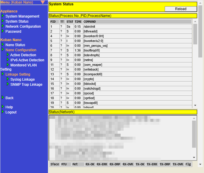
The following information can be checked about the Nano System Status.
| Item | Description |
|---|---|
Status(Process:No.,PID,ProcessName) |
Displays the information on processes running in the Nano. |
Status(Network) |
Displays the information on the Nano interface. |
Status(Service,Daemon) |
Displays the information on services running in the Nano. |
Status(Disk) |
Displays the contents of the disk used by Nano. |
Status(NTP) |
Displays the NTP information configured in the Nano. |
Displays the information on Syslog Linkage, SNMP Trap Linkage. |
|


Syslog/SNMP Trap Linkage
Syslog/SNMP Trap Linkage information displays information related to Syslog Linkage and SNMP Trap Linkage .

There are the following items to check.
| Item | Description |
|---|---|
Type |
Displays the name of the link target. |
Received |
Displays the number of Syslog messages or SNMP Traps received by Nano.
|
Processed |
Displays the number of Syslog messages or SNMP Traps received by Nano that match the Linkage settings and conditions and are processed by the Linkage action.
|
Displays the number of processed Syslog messages or SNMP Traps for which Mail actions were executed. |
|
Blocking |
Displays the number of processed Syslog messages or SNMP Traps for which Blocking actions were executed . |
If the Syslog Linkage function or SNMP Trap Linkage function is disabled, - (hyphen) is displayed .
|
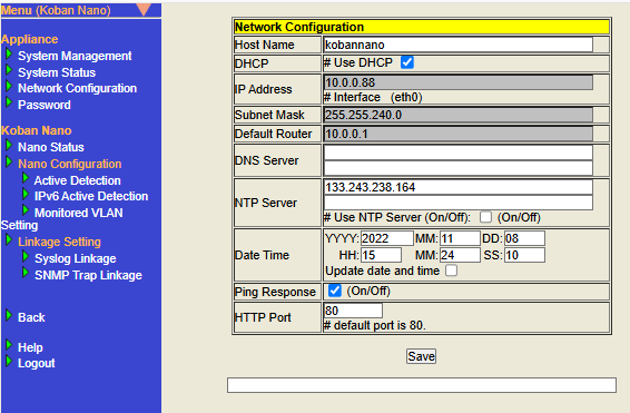
Network Configuration
Change the Host Name
Changing the Host Name will change the URL used to access Nano via Bonjour.
-
Open Nano Setting/Network Setting
Click on Nano Management > Nano Setting/Network Setting in the top menu.
-
Open Network Configuration screen
Click Network Configuration in the menu on the left side of the screen.
-
Set the Host Name
Enter a host name using single-byte alphanumeric characters without spaces. The host name (excluding the domain name) must be 63 characters or fewer, while the FQDN can be up to 253 characters.
-
Save settings
Click Save at the bottom of the screen. Host Name settings are saved.
Network Configuration
For DHCP configuration
(1) If "# Use DHCP" is selected and the address can be obtained from DHCP, then Nano will use the address obtained from DHCP.
(2)
If "# Use DHCP" is selected and the address cannot be obtained from DHCP, then Nano will use the address in the 169.254.0.0/16 network.
(3) If "# Use DHCP" is not selected, then Nano will use the IP address specified in the network configuration.
-
Open Nano Setting/Network Setting
Please click on "Nano Management" > "Nano Setting/Network Setting" in the top menu.
-
Open the Network Configuration screen
Click on "Network Configuration" from the menu on the left side of the screen.
-
Setup DHCP
Select "# Use DHCP" checkbox for using DHCP.
-
Setting up a network without using DHCP
Uncheck "# Use DHCP" and set the IP Address, Subnet Mask and Default Router respectively.
-
Save the settings
Click on Save at the bottom of the screen. DHCP configuration is saved.
DNS Server Settings
For DNS Server settings
(1) If a DNS Server is specified in the Network Configuration: The specified DNS Server is used with or without the DNS Server assigned by the DHCP Server.
(2) If no DNS Server is specified in the Network Configuration: If "# Use DHCP" is selected and the DNS Server can be obtained from DHCP, the DNS Server obtained from DHCP will be used.
(3) The Host Name cannot be resolved by Nano except in cases (1) and (2). In this case, the Mail server in the Action Settings must be specified by IP Address.
-
Open Nano Setting/Network Setting
Click on "Nano Management" > "Nano Setting/Network Setting" in the top menu.
-
Open the Network Configuration screen
Click on "Network Configuration" from the menu on the left side of the screen.
-
Set the DNS Server
To specify a DNS Server, enter the IP address of the DNS Server (maximum two).
-
Save the settings
Click Save at the bottom of the screen. DNS Server settings are saved.
NTP Server Settings
To use NTP, check the check box "# Use NTP Server" and specify the NTP server.
-
Open Nano Setting/Network Setting
Click on "Nano Management" > Nano Setting/Network Setting" in the top menu.
-
Open the Network Configuration screen
Click on "Network Configuration" from the menu on the left side of the screen.
-
Set NTP Server
Enter the IP address or FQDN of any NTP server in the NTP Server field. Maximum of two NTP servers can be set.
Check to set the time using NTP. -
Save the settings
Click on "Save" at the bottom of the screen. NTP server settings are saved.
Set system time
There is a possibility that if the system time is not correct, operational reports will not be generated properly. Set the system time from Nano Setting (Web screen).
-
Open Nano Setting/Network Setting
Click on the top menu "Nano Management" > "Nano Setting/Network Setting".
-
Open Network Configuration
Click on "Network Configuration" from the menu on the left side of the screen.
-
Set the date and time
Set the current time to Date Time
YYYY(AD),MM(month),DD(day),HH(hour <24h>),MM(minute),SS(second). -
Update date and time
Check the box if you want to update the date and time.
-
Save the settings
Click Save at the bottom of the screen. The time setting is saved.
Ping Response Settings
When Ping Response is enabled, the reachability of Nano can be checked by Ping from other hosts.
Check the checkbox, to enable Ping Response.
Uncheck to stop responding to Ping.
-
Open Nano Setting/Network Setting
Click on "Nano Management" > "Nano Setting/Network Setting" in the top menu.
-
Open the Network Configuration screen
Click on "Network Configuration" from the menu on the left side of the screen.
-
Set Ping Response
Check the box of Ping Response to switch On/Off.
-
Save the settings
Click on "Save" at the bottom of the screen. Ping Response settings are saved.
Set HTTP Port
Set the port number that HTTP server accepts from HTTP client.
If a port other than 80 is set, then specify the port number while accessing from the browser using the URL. (for example: http://192.168.0.1:8000/)
-
Open Nano Setting/Network Setting
Click on Nano Management > Nano Setting/Network Setting in the top menu.
-
Open Network Configuration screen
Click Network Configuration in the menu on the left side of the screen.
-
Set HTTP Port
Enter any port number in the HTTP Port field. You can set a port number between 0 and 65535. The default is port 80.
-
Save settings
Click Save at the bottom of the screen. HTTP Port setting is saved.
Change Password
Change the password for logging in to the Nano web screen.
-
Open Nano Setting/Network Setting
Please click on Top menu Nano Management > Nano Setting/Network Setting.
-
Open Password Change screen
Click on the Password in the menu on the left.
-
Password Change
Enter the current password and the new password, click on Change.
The Passwords must be between 6 and 64 characters in length.
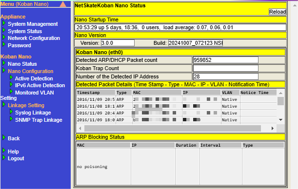
Nano Status
The status as the Nano can be checked with Nano Status. [Note1]
The following items can be confirmed from the Nano Status screen.
| Item | Description |
|---|---|
Nano Boot up |
Displays current time and running days and time from boot up to current. |
Nano Version |
Displays Version information and build number of Nano. |
Koban Nano (eth0) |
Displays |
Detected Packet Details |
Displays detail information of detected packet. |
ARP Blocking Status |
Displays ARP blocking status of Nano. |
Click the "Reload" button at the top of the page to update each item with the latest information.
|
The item Koban Trap Count in Koban Nano (eth0) isn’t used on Nano.
|
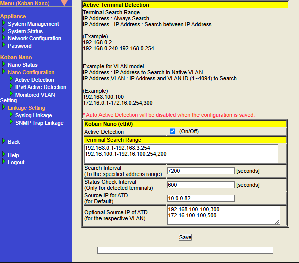
Active Detection
"Active Detection" is a function that sends ARP requests based on the settings configured on the settings screen to actively detect network terminals (such as printers) that rarely send ARP packets.
Note that if you enable Auto Active Detection in Action Settings, the settings on this screen will be executed automatically. Please configure on this screen only if you need to send an ARP request with detailed settings.
This function detects only terminals with IPv4 addresses. If you want to execute Active Detection on a terminal with an IPv6 address, please use "IPv6 Active Detection".
- Display the Active Detection screen
-
Click the links in the following order to display.
-
Click on Nano Management > Nano Setting/Network Setting on the top menu to display the Nano Setting/Network Setting screen.
-
Click on "Active Detection" on the left menu.
-
- Configure Active Detection settings
-
The settings will be reflected by configuring and saving each setting item and rebooting the system. Below are the operating steps.
-
Display the Active Detection screen, configure each setting item appropriately, and then click the "Save" button.
※Please refer to table below for information on how to configure each setting item. -
The following message will be displayed, Click "OK".
Do you really want to save Active Terminal Detection configuration? ※Saved configuration will be applied after reboot. -
When the saving is complete, the message
Configuration savedwill be displayed at the bottom of the screen. -
Perform a Reboot. For information on how to reboot, please refer to Restart Nano.
-
|
Item |
Description |
Default Value |
Value that is automatically configured when Auto Active Detection in Action Settings is enabled |
|||
|---|---|---|---|---|---|---|
Nano |
||||||
Active Detection |
Check the box to enable the Active Detection function. |
Unchecked (Disabled) |
Checked (Enabled) |
Checked (Enabled). |
||
Configure the IP address range for Active Detection. Please configure the IP address in IPv4 format.
If you want to configure a continuous range, please configure the starting IP address and ending IP address by connecting them with a
If you want to configure multiple conditions, please separate them with line breaks to create multiple lines.
In Nano(V), it is necessary to configure the Search Range for each VLAN ID.
|
Blank |
Value based on "IP Address" and "Subnet Mask" of Network Configuration
|
|
|||
Search Interval |
Configure the interval to execute Active Detection. The unit is seconds. Please configure an integer greater than or equal to 1. This Active Detection process is executed for the IP address configure in Terminal Search Range Settings. This is a required input field. |
7200 |
7200 |
7200 |
||
Status Check interval |
Configure the interval to execute Active Detection. The unit is seconds. Please configure an integer greater than or equal to 1. This Active Detection process is executed for the IP address of the terminal being detected. For detected terminals, please refer to Detected Terminal List. This is a required input field. |
600 |
600 |
600 |
||
Configure the source IP address of the terminal detection packet sent during Active Detection. For the source IP address, please configure the IP address in IPv4 format. This is a required input field.
|
0.0.0.0 |
"IP Address" value in Network Configuration
|
"IP Address" value in Network Configuration
|
|||
Configure the source IP address of each VLAN ID of the terminal detection packet sent for Active Detection. For the source IP address of each VLAN ID, configure the IP address in IPv4 format, then add a
|
Blank |
- |
Value that combines each "VLAN ID" whose Monitoring is enabled in the Monitored VLAN Settings and its "Source IP"
|
|||
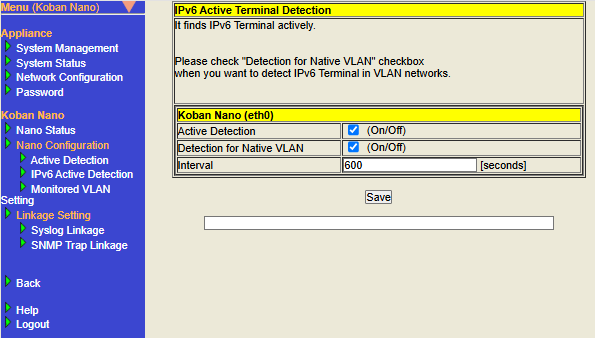
IPv6 Active Terminal Detection
"IPv6 Active Detection", like "Active Detection", is a function that allows you to actively detect network terminals that are normally difficult to detect. ICMPv6 packets are sent based on the settings configured on the settings screen.
- Display the IPv6 Active Detection screen
-
Click the links in the following order to display.
-
Click on Nano Management > Nano Setting/Network Setting on the top menu to display the Nano Setting/Network Setting screen.
-
Click on "IPv6 Active Detection" on the left menu.
-
- Configure IPv6 Active Detection
-
The settings will be reflected by configuring and saving each setting item and rebooting the system. Below are the operating steps.
-
Display the IPv6 Active Detection screen, configure each setting item appropriately, and then click the "Save" button.
※Please refer to table below for information on how to configure each setting item. -
The following message will be displayed, Click "OK".
Do you really want to save IPv6 Active Terminal Detection configuration? ※Saved configuration will be applied after reboot. -
When the saving is complete, the message
Configuration savedwill be displayed at the bottom of the screen. -
Perform a Reboot. For information on how to reboot, please refer to Restart Nano.
-
| Item | Description | Default Value | ||
|---|---|---|---|---|
Active Detection |
Check the box to enable the IPv6 Active Detection function. |
Unchecked (Disabled) |
||
Detection for Native VLAN |
|
Unchecked (Disabled) |
||
Interval |
Configure the interval for executing IPv6 Active Detection. The unit is seconds. Please configure an integer greater than or equal to 1. This IPv6 Active Detection process is executed for IPv6 addresses. This is a required input field. |
600 |
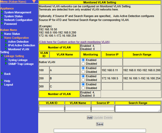
Monitored VLAN Setting
By setting the VLAN you want to monitor, the terminals connected to that VLAN network can be monitored.
| This function is exclusively for Nano(V). |
If the VLAN information configured in the Monitored VLAN Setting matches the VLAN information of the observed packet (= VLAN ID of the VLAN tag according to IEEE 802.1Q), the terminal information will be displayed in Detected Terminal List.
- About Native VLAN
-
Packets without an IEEE 802.1Q compliant VLAN tag are treated as "Native VLAN".
|
What can be configured with Monitored VLAN Setting
"Monitored VLAN Setting" allows you to configure the following settings to detect terminals connected to the VLAN network.
- Add VLAN information to monitor
-
By adding information about the VLAN to be monitored, terminals connected to each VLAN network can be detected. The maximum number of VLANs that can be added (※including the number of Native VLAN) with Monitoring enabled is 10 for NSK-NANO-VB0AX and 40 for NSK-NANO-VB4AX.
-
Related setting items
-
- For each VLAN information, configure "Setting whether to detect terminals" and "Setting whether to execute Auto Detection using Auto Active Detection"
-
"Setting whether to detect terminals or not" and "Setting whether to execute Auto Detection using Auto Active Detection" are linked.
If configuration item Monitoring is enabled, terminals will be detected and Auto Detection will be executed using Auto Active Detection.
If configuration item Monitoring is disabled, the terminal will not be detected and Auto Detection will not be executed using Auto Active Detection.However, this is an exceptional behavior for Native VLAN, which means that terminals will be detected (= the ability to detect terminals will not be disabled), and Auto Detection using Auto Active Detection will no longer be executed.-
Related setting items
-
- For each VLAN ID, configure the base value for Active Detection settings
-
If you enable Auto Active Detection in Action Settings, Active Detection settings will be configured automatically. The base values for the settings can be configured to "Source IP" and "Search Range".
-
About the base value of the Active Detection setting of Native VLAN For Native VLAN, the "IP address" and "Subnet Mask" of Network Configuration are the base values for the Active Detection settings.
-
The value of "IP Address" in Network Configuration will be used as the Source IP of ATD in Active Detection.
-
The value of "IP Address" and "Subnet Mask" in Network Configuration will be used Terminal Search Range in Active Detection
-
-
Related setting item name
-
Before use
VLAN tagged packets and VLAN untagged packets conforming to IEEE 802.1Q are monitored.
For the trunk port connecting Nano(V), please configure the Ethernet switch so that packets of the VLAN to be monitored can be properly sent and received as packets with VLAN tags and packets without VLAN tags.
Display the Monitored VLAN Setting screen
- Click the links in the following order to display them.
-
-
Click Nano Management > Nano Setting/Network Setting on the top menu to display the Nano Setting/Network Setting screen.
-
Click Monitored VLAN Setting on the left menu.
-
Configure Monitored VLAN Setting
|
- Add Monitored VLAN Setting
-
After configuring, adding, and saving each setting item, the settings will be reflected by rebooting the system. Below are the operating steps.
-
Display the Monitored VLAN Setting screen, configure each setting item appropriately, and then click the "Add" button.
※Please refer to table below for information on how to configure each setting item.
-
Click the "Save" button.
-
The following message will be displayed, Click "OK".
Do you really want to save Monitored VLAN Setting? ※Saved configuration will be applied after reboot. -
When saving is complete, the message
Monitored VLAN Setting is saved.will be displayed at the bottom of the screen. -
Perform a Reboot. For information on how to reboot, please refer to Restart Nano.
-
- Update Monitored VLAN Setting
-
After selecting an existing setting item, then configuring, adding, and saving each setting item, the settings will be reflected by rebooting the system. Below are the operating steps.
-
Display the Monitored VLAN Setting screen and click the row for the existing Monitored VLAN Setting. After clicking, the row becomes selected (the background is blue).
-
After configuring each setting item appropriately, click the "Update" button.
※Please refer to table below for information on how to configure each setting item.
-
Click the "Save" button.
-
The following message will be displayed, Click "OK".
Do you really want to save Monitored VLAN Setting? ※Saved configuration will be applied after reboot. -
When saving is complete, the message
Monitored VLAN Setting is saved.will be displayed at the bottom of the screen. -
Perform a Reboot. For information on how to reboot, please refer to Restart Nano.
-
- Delete Monitored VLAN Setting
-
After selecting an existing setting item, then deleting, and saving each setting item, the settings will be reflected by rebooting the system. Below are the operating steps.
-
Display the Monitored VLAN Setting screen and click the line for the existing Monitored VLAN Setting. After clicking, the row becomes selected (the background is blue).
-
Click the "Delete" button. At this point, the line for Monitored VLAN Setting will be removed from the screen.
-
Click the "Save" button.
-
The following message will be displayed, click "OK".
Do you really want to save Monitored VLAN Setting? ※Saved configuration will be applied after reboot. -
When saving is complete, the message
Monitored VLAN Setting is saved.will be displayed at the bottom of the screen. -
Perform a Reboot. For information on how to reboot, please refer to Restart Nano.
-
| Item | Description | Default Value | ||
|---|---|---|---|---|
Configure the VLAN ID (integer from 1 to 4094) of the VLAN you want to monitor. This is a required input field.
|
Blank |
|||
Configure any name for the VLAN you want to monitor (Optional).
|
Blank |
|||
Configure terminal detection and Auto Active Detection settings for the added Monitored VLAN Setting. You can select enable or disable.
|
Enabled |
|||
Configure the source IP address when executing Active Detection. If "Auto Active Detection in Action Settings is enabled" and "Monitoring is enabled", the combination of Source IP value and VLAN ID value will be configured in the "Optional Source IP of ATD(for the respective VLAN)" for Active detection". For the Source IP address, please configure the IP address in IPv4 format. This configuration is required if there is an input in the Search Range of the same setting row.
|
Blank |
|||
Configure the search range when executing Active Detection. The value configured in this item will be referenced as the Active Detection Search Range when Auto Active Detection settings are executed. If "Auto Active Detection in Action Settings is enabled" and "Monitoring is enabled", the combination of this search range value and VLAN ID value will be configured in the "Search Range" for Active Detection. Configure the IP address search range by connecting the starting IP address and ending IP address with a This configuration is required if there is an input for the Source IP in the same setting line.
To configure multiple conditions, please separate them with line breaks to create multiple lines.
|
Blank |
About the relationship between Monitored settings and Auto Active Detection settings
Monitored settings are related to the operation of terminal detection for the Monitored VLAN and the auto configuration results of Active Detection using Auto Active Detection.
The table below shows the settings, contents, and results.
Setting target |
Settings(1) |
Settings(2) |
Setting Result(1) |
Setting Result(2) |
||
|---|---|---|---|---|---|---|
Type of VLAN for Monitoring settings |
Setting Monitoring |
Setting Auto Action Detection value of Action Setting |
Detected/Not Detected |
Active Detection target items and setting values that are |
||
Target items (1) |
Target items (2) |
Target items (3) |
||||
Disabled |
Disabled |
Detected |
No setting |
No setting |
(Not applicable) |
|
Enabled |
No setting |
The "IP Address" value of Network Configuration is configured. |
||||
Enabled |
Disabled |
No setting |
No setting |
|||
Enabled |
The "IP Address" and "Subnet Mask" value of Network Configuration is configured. |
The "IP address" value of Network Configuration is configured. |
||||
Disabled |
Disabled |
Not Detected |
No setting |
(Not applicable) |
No setting |
|
Enabled |
No setting |
No setting |
||||
Enabled |
Disabled |
Detected |
No setting |
No setting |
||
Enabled |
The value that is a combination of VLAN ID and Search Range of the Monitored VLAN Setting is configured. |
The value that is a combination of VLAN ID and Source IP of the Monitored VLAN Setting is configured. |
||||
Notes on saving Monitored VLAN Setting
If "DHCP settings of Network Configuration are enabled", the Monitored VLAN Setting saved by clicking the "Save" button may be reflected without requiring a reboot.
This behavior occurs when Nano automatically changes its settings in response to automatic IP address assignment by DHCP.
- Examples of behavior where the Monitored VLAN Setting are reflected without requiring a reboot when the DHCP settings in the Network Configuration are enabled
-
-
Edit the Monitored VLAN Setting and click the "Save" button to save the settings (※Do not reboot at this point).
-
When automatic IP address assignment by DHCP occurs, Nano’s IP Address and Subnet Mask (= "IP Address" and "Subnet Mask" in Network Configuration) will be updated.
-
The operation in
2.will trigger the Monitored VLAN Setting saved in1.to be reflected. -
If Auto Active Detection of Action Settings is enabled, the Monitored VLAN Setting saved in `1. will be configured and reflected in <ActionSettings-table_AutoActiveDetection, Auto Active Detection>> in Action Settings. (※If Auto Active Detection in Action Settings is disabled, this step will not occur).
-
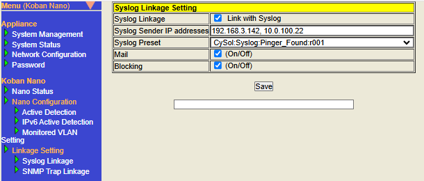
Syslog Linkage Setting
By receiving Syslog messages from linked terminals, Nano can execute Mail and Blocking actions based on the settings in "Syslog linkage" settings.
- Display the Syslog Linkage Setting screen
-
Click the links in the following order to display.
-
Click Nano Management > Nano Setting/Network Setting on the top menu to display the Nano Setting/Network Setting screen.
-
Click Syslog Linkage on the left menu.
-
- Configure Syslog Linkage
-
The settings will be reflected by configuring and saving each setting item and rebooting the system. Below are the operating steps.
-
Display the Syslog Linkage Setting screen, configure each setting item appropriately, and then click the "Save" button.
※Please refer to table described later for how to configure each setting item. -
The following message will be displayed, Click "OK".
Do you really want to save Syslog Linkage Setting? ※Saved configuration will be applied after reboot. -
When the saving is complete, the message
Linkage Setting saved successfully.will be displayed at the bottom of the screen. -
Perform a reboot. For information on how to reboot, please refer to Restart Nano.
-
| Item | Description | Default Value | ||||||||||||
|---|---|---|---|---|---|---|---|---|---|---|---|---|---|---|
Check the box to enable the Syslog Linkage function.
|
Unchecked (Disabled) |
|||||||||||||
Configure the source IP address of the Syslog messages received by the Syslog Linkage function. Only Syslog messages sent from terminals with the IP address configured here will be linked. For the source IP address, please configure the IP address in IPv4 format.
If you want to configure multiple senders, please configure them separated by
This configuration is required, if Syslog Linkage is enabled. |
Blank |
|||||||||||||
Select and configure a preset name from the list that matches the target to be linked with Syslog Linkage (= terminal that sends Syslog messages and its functions). This configuration is required, if Syslog Linkage is enabled. |
Blank |
|||||||||||||
Check the box to enable the Mail action from the Syslog Linkage settings. A mail containing the terminal information (IP address, MAC address) notified in the Syslog message will be sent. |
Unchecked (Disabled) |
|||||||||||||
Check the box to enable the Blocking action from the Syslog Linkage settings. Performs Blocking on the terminal notified by Syslog message. |
Unchecked (Disabled) |
Notes on actions based on Syslog Linkage
Actions based on Syslog Linkage include Mail and Blocking. The "action" described below refer to both Mail and Blocking.
-
About the conditions for executing the action
-
The action will be executed when all of the following conditions are met:
-
The Syslog message received by Nano, the IP address of the terminal that sent the Syslog message matches Syslog Sender IP addresses.
-
The Syslog messages received by Nano, the Syslog message type matches Preset.
-
The Syslog message received by Nano, the terminal corresponding to the terminal information (= target of action) included in the Syslog message is detected in Detected Terminal List.
※For the terminal information targeted by the action, please refer to Presets List (Syslog Linkage) below.
-
-
-
About the type of IP addresses to execute the action
-
If the target to execute an action on is an IPv4 address, the action will not be executed on the IPv6 address even if the terminal with that IPv4 address also has an IPv6 address.
-
-
About advanced setting for action to be executed
-
when an unregistered terminal is detected, each setting item is same as the Auto Action in Action Settings.
-
Mail is configured in Mail Configuration and SMTP Configuration in Action Settings.
-
Blocking is configured in Blocking Configuration in Action Settings.
-
-
-
About settings unrelated to execution of action based on Syslog Linkage
-
The following settings are not related to the execution of Syslog Linkage actions.
-
Auto Action when unregistered terminal is detected
-
Action based on Syslog Linkage will be executed even if Auto Action are disabled when unregistered terminals are detected.
-
Example 1) If Mail action of Syslog Linkage is enabled, Mail action (= Auto Action (Default) or Custom action for each monitoring VLAN) of Action Settings is disabled. Mail action of Syslog Linkage will be executed.
※The Custom action for each monitoring VLAN function is available only in Nano(V).
-
Example 2) If Blocking action of Syslog Linkage is enabled, Blocking action (= Auto Action (Default) or Custom action for each monitoring VLAN) of Action Settings is disabled. Blocking of Syslog Linkage action will be executed.
※The Custom action for each monitoring VLAN function is available only in Nano(V).
-
-
-
ATL
-
Action based on Syslog Linkage will be executed even if the target terminal is registered in ATL.
-
-
Safe Mode
-
Action based on Syslog Linkage will be executed even if Safe Mode of Action Settings is configured to enabled.
-
-
-
-
Mechanism to prevent the same action from being executed continuously in short time intervals
-
Action based on "Syslog Linkage/SNMP Trap Linkage" for the same MAC address will not be re-executed for 1 minute after being executed.
-
When an action based on Syslog Linkage is executed for a MAC address
-
Check "Target MAC address of action" and "Target MAC address of Syslog Linkage/SNMP Trap Linkage action in the last minute" to determine whether to re-execute.
-
-
When an action based on Syslog Linkage is executed for an IP address
-
Judgment will be made in the following order.
-
The MAC address obtained by linking the "Action target IP address" with the "IP address information of the terminals detected in the Detected Terminal List is configured as the "Action target MAC address".
-
Check the "Action target MAC address" specified in
1and the "target MAC address of the Syslog Linkage/SNMP Trap Linkage action in the last minute" to determine whether to re-execute.
-
-
-
-
Preset List (Syslog Linkage)
Below are the names of each preset and the interpretation of Syslog messages sent by the corresponding products and features.
| Preset name | Syslog source product corresponding to Preset name | Description |
|---|---|---|
|
Trend Micro |
Compatible with Syslog messages sent from Trend Micro Network Monitoring Products. This applies to Syslog messages that contain the strings Syslog Linkage actions are executed for the terminal with the IP address written in |
|
Virtual Products |
Compatible with Syslog messages sent for the purpose of operation verification. This applies to Syslog messages that contain the strings Syslog Linkage actions are executed for the terminal with the IP address written in |
|
SonicWall |
Compatible with Syslog messages related to content filtering prohibited URL access sent from SonicWall Firewall Products. This applies to Syslog messages that contain the string Syslog Linkage actions are executed for the terminal with the IP address written in Reference: Information about linked products > Event name |
|
SonicWall |
Compatible with gateway antivirus-related Syslog messages sent from SonicWall Firewall Products. This applies to Syslog messages that contain the string Syslog Linkage actions are executed for the terminal with the IP address written in Reference: Information about linked products > Event name |
|
SonicWall |
Compatible with intrusion prevention system-related Syslog messages sent from SonicWall Firewall Products. This applies to Syslog messages that contain the string Syslog Linkage actions are executed for the terminal with the IP address written in Reference: Information about linked products > Event name |
|
SonicWall |
Compatible with intrusion detection system-related Syslog messages sent from SonicWall Firewall Products. This applies to Syslog messages that contain the string Syslog Linkage actions are executed for the terminal with the IP address written in Reference: Information about linked products > Event name |
|
SonicWall |
Compatible with Syslog messages related to Botnet detection sent from SonicWall Firewall Products. This applies to Syslog messages that contain the string Syslog Linkage actions are executed for the terminal with the IP address written in Reference: Information about linked products > Event name |
|
Fortinet |
Compatible with IPS-related, anomaly-related, virus detection-related, web filter-related, or dns filter-related Syslog messages sent from Fortinet Firewall Products. The syslog message contains the string This applies to Syslog Linkage actions are executed for the terminal with the IP address written in Reference: Information about linked products > Event name |
|
Fortinet |
Compatible with IPS-related Syslog messages sent from Fortinet Firewall Products. This applies to Syslog messages that contain the string Syslog Linkage actions are executed for the terminal with the IP address written in Reference: Information about linked products > Event name |
|
Fortinet |
Compatible with anomaly-related Syslog messages sent from Fortinet Firewall Products. This applies to Syslog messages that contain the string Syslog Linkage actions are executed for the terminal with the IP address written in Reference: Information about linked products > Event name |
|
Fortinet |
Compatible with virus detection-related Syslog messages sent from Fortinet Firewall Products. This applies to Syslog messages that contain the string Syslog Linkage actions are executed for the terminal with the IP address written in Reference: Information about linked products > Event name |
|
Fortinet |
Compatible with web filter-related Syslog messages sent from Fortinet Firewall Products. This applies to Syslog messages that contain the string Syslog Linkage actions are executed for the terminal with the IP address written in Reference: Information about linked products > Event name |
|
Fortinet |
Compatible with dns filter-related Syslog messages sent from Fortinet Firewall Products. This applies to Syslog messages that contain the string Syslog Linkage actions are executed for the terminal with the IP address is specified in the Reference: Information about linked products > Event name |
|
Fortinet |
Supports Botnet-related Syslog messages sent by Fortinet firewall products. The syslog messages that contain the strings Syslog linkage actions are executed for the terminal whose IP address is specified in the Reference: Information about linked products > Event name |
|
Fortinet |
Supports Sandbox-related Syslog messages sent from Fortinet firewall products. The syslog messages that contain the strings Syslog linkage actions are executed for the terminal whose IP address is specified in the Reference: Information about linked products > Event name |
Operation confirmation of Syslog Linkage
Display the System Status screen, check the contents of "Syslog/SNMP Trap Linkage" there, and check the operation results of the Syslog Linkage function.
-
Display the System Status screen. For details on how to display, refer to Display the System Status screen.
-
Display "Syslog/SNMP Trap Linkage" at the bottom of the System Status screen.
-
Look at the displayed content and check whether Syslog Linkage is being executed. For details on how to check the displayed items, see Syslog/SNMP Trap Linkage.
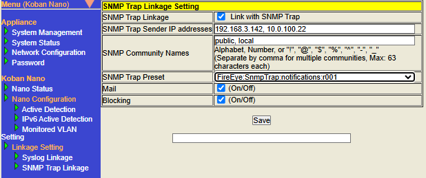
SNMP Trap Linkage Setting
By receiving SNMP Traps from linked terminals, Nano can execute Mail and Blocking actions based on the settings in the "SNMP Trap Linkage" settings.
- Display the SNMP Trap Linkage settings screen
-
Click the links in the following order to display.
-
Click Nano Management > Nano Setting/Network Setting on the top menu to display the Nano Setting/Network Setting screen.
-
Click SNMP Trap Linkage on the left menu.
-
- Configure SNMP Trap Linkage
-
The settings will be reflected by configuring and saving each setting item and rebooting the system. Below are the operating steps.
-
Display the SNMP Trap Linkage settings screen, configure each setting item appropriately, and then click the "Save" button.
※Please refer to table below for information on how to configure each setting item. -
The following message will be displayed, Click "OK".
Do you really want to save SNMP Trap Linkage Setting? ※Saved configuration will be applied after reboot. -
When the saving is complete, the message
Linkage Setting saved successfully.will be displayed at the bottom of the screen. -
Perform a reboot. For information on how to reboot, please refer to Restart Nano.
-
| Item | Description | Default Value | ||||||||||||||
|---|---|---|---|---|---|---|---|---|---|---|---|---|---|---|---|---|
Check the box to enable the SNMP Trap Linkage function.
|
Unchecked (Disabled) |
|||||||||||||||
Configure the source IP address of the SNMP Trap received by the SNMP Trap Linkage function. Only SNMP Traps sent from the IP address configure here will be linked. For the source IP address, please configure the IP address in IPv4 format.
If you want to configure multiple senders, please configure them separated by
This configuration is required, if SNMP Trap Linkage is enabled. |
Blank |
|||||||||||||||
Configure the SNMP Trap community name. Multiple community names can be configured. For each community name, you can configure up to 63 characters including half-width letters, numbers, and symbols (
If you want to configure multiple community names, please configure them separated by
This configuration is required, if SNMP Trap Linkage is enabled. |
Blank |
|||||||||||||||
Select and configure a preset name from the list that matches the target (= terminal that sends SNMP Traps and its functions) to be linked with SNMP Trap Linkage. This configuration is required, if SNMP Trap Linkage is enabled. |
Blank |
|||||||||||||||
Check the box to enable Mail action from the SNMP Trap Linkage settings. A mail containing the terminal information (IP address, MAC address) notified by SNMP Trap will be sent. |
Unchecked (Disabled) |
|||||||||||||||
Check the box to enable Blocking action from the SNMP Trap Linkage settings. Executes Blocking against the terminal notified by SNMP Trap. |
Unchecked (Disabled) |
Notes on actions based on SNMP Trap Linkage
Actions based on SNMP Trap Linkage include Mail and Blocking. The "action" described below refers to both Mail and Blocking.
-
About the conditions for executing the action
-
The action will be executed when all of the following conditions are met:
-
The SNMP Trap received by Nano, the IP address of the terminal that sent the SNMP Trap matches SNMP Trap Sender IP addresses.
-
The SNMP Trap received by Nano, the community name of the SNMP Trap matches SNMP Community Names.
-
The SNMP Trap received by Nano, the SNMP Trap type matches SNMP Trap Preset.
-
The SNMP Trap received by Nano, the terminal corresponding to the terminal information (= target of action) included in the SNMP Trap is detected in Detected Terminal List.
※For the terminal information targeted by the action, please refer to Preset list (SNMP Trap Linkage) below.
-
-
-
About the type of IP address to execute the action
-
If the target to execute an action on is an IPv4 address, the action will not be executed on the IPv6 address even if the terminal with that IPv4 address also has an IPv6 address.
-
-
About detailed settings for action to be executed
-
when an unregistered terminal is detected, each setting item is same as the Auto Action in Action Settings.
-
Mail is configured in Mail Configuration and SMTP Configuration in Action Settings.
-
Blocking is configured in Blocking Configuration in Action Settings.
-
-
-
About settings unrelated to the execution of action based on SNMP Trap Linkage
-
The following settings are not related to the execution of SNMP Trap Linkage actions.
-
Auto Action when unregistered terminal is detected
-
Action based on SNMP Trap Linkage will be executed even if Auto Action are disabled when unregistered terminals are detected.
-
Example 1) If Mail action of SNMP Trap Linkage is enabled, Mail action (= Auto Action (Default) or Custom action for each monitoring VLAN) of Action Settings is disabled. Mail action of SNMP Trap Linkage will be executed.
※The Custom action for each monitoring VLAN function is available only in Nano(V).
-
Example 2) If Blocking action of SNMP Trap Linkage is enabled, Blocking action (= Auto Action (Default) or Custom action for each monitoring VLAN) of Action Settings is disabled. Blocking of SNMP Trap Linkage action will be executed.
※The Custom action for each monitoring VLAN function is available only in Nano(V).
-
-
-
ATL
-
Action based on SNMP Trap Linkage will be executed even if the target terminal is registered in ATL.
-
-
Safe Mode
-
Action based on SNMP Trap Linkage will be executed even if Safe Mode of Action Settings is enabled.
-
-
-
-
Mechanism to prevent the same action from being executed continuously in short time intervals
-
Action based on "Syslog Linkage/SNMP Trap Linkage" for the same MAC address will not be re-executed for 1 minute after being executed.
-
When an action based on SNMP Trap Linkage is executed for a MAC address
-
Check "Target MAC address of action" and "Target MAC address of Syslog Linkage/SNMP Trap Linkage action in the last minute" to determine whether to re-execute.
-
-
When an action based on SNMP Trap Linkage is executed for an IP address
-
Judgment will be made in the following order.
-
TThe MAC address obtained by linking the "Action target IP address" with the " IP address information of the terminals detected in the Detected Terminal List" is configured as the "Action target MAC address".
-
Check the "Action target MAC address" specified in
1and the "target MAC address of the Syslog Linkage/SNMP Trap Linkage action in the last minute" to determine whether to re-execute.
-
-
-
-
Preset list (SNMP Trap Linkage)
Below are the names of each preset and the interpretation of SNMP Traps sent by the corresponding products and features.
| Preset Name | SNMP Trap source product corresponding to Preset name | Description |
|---|---|---|
|
FireEye |
Compatible with SNMP Traps sent by FireEye Security Products. This applies to SNMP Traps whose OID matches SNMP Trap Linkage actions are executed for the terminal with the IPv4 address included in the SNMP Trap Varbind |
|
Fortinet |
Compatible with IPS-related SNMP Traps sent from Fortinet Firewall Products. This applies to SNMP Traps whose OID matches SNMP Trap Linkage actions are executed for the terminal with the IPv4 address included in the SNMP Trap Varbind Reference: Information about linked products Event name |
|
Fortinet |
Compatible with anomaly-related SNMP Traps sent from Fortinet Firewall Products. This applies to SNMP Traps whose OID matches SNMP Trap Linkage actions are executed for the terminal with the IPv4 address included in the SNMP Trap Varbind Reference: Information about linked products Event name |
|
Sample for operation verification |
Compatible with SNMP Traps sent for operation verification. This applies to SNMP Traps whose OID matches SNMP Trap Linkage actions are executed for the terminal with the IPv4 address included in the SNMP Trap Varbind |
|
SonicWall |
Compatible with SNMP Traps related to content filter prohibited URL access sent from SonicWall Firewall Products. The SNMP Trap OID matches SNMP Trap Linkage actions are executed for the terminal with the IPv4 address included in the SNMP Trap Varbind Reference: Information about linked products Event name |
|
SonicWall |
Compatible with gateway antivirus-related SNMP Traps sent from SonicWall Firewall Products. The SNMP Trap OID matches SNMP Trap Linkage actions are executed for the terminal with the IPv4 address included in the SNMP Trap Varbind Reference: Information about linked products Event name |
|
SonicWall |
Compatible with intrusion prevention system-related SNMP Traps sent from SonicWall Firewall Products. The SNMP Trap OID matches SNMP Trap Linkage actions are executed for the terminal with the IPv4 address included in the SNMP Trap Varbind Reference: Information about linked products Event name |
|
SonicWall |
Compatible with intrusion detection system-related SNMP Traps sent from SonicWall Firewall Products. The SNMP Trap OID matches SNMP Trap Linkage actions are executed for the terminal with the IPv4 address included in the SNMP Trap Varbind Reference: Information about linked products Event name |
|
Trend Micro |
Compatible with virus infection-related SNMP Traps sent from Trend Micro Network Monitoring Products. This applies to SNMP Traps whose OID matches SNMP Trap Linkage actions are executed for the terminal with the IPv4 address included in the SNMP Trap Varbind |
|
Trend Micro |
Compatible with virus detection-related SNMP Traps sent from Trend Micro Network Monitoring Products. This applies to SNMP Traps whose OID matches SNMP Trap Linkage actions are executed for the terminal with the IPv4 address included in the SNMP Trap Varbind |
Confirming the operation of SNMP Trap Linkage
Display the System Status screen, check the contents of "Syslog/SNMP Trap Linkage" there, and check the operation results of the SNMP Trap Linkage function.
-
Display the System Status screen. For details on how to display, refer to Display the System Status screen.
-
Display the "Syslog/SNMP Trap Linkage" at the bottom of the System Status screen.
-
Look at the displayed content and check whether SNMP Trap Linkage is being executed. For details on how to check the displayed items, see <<Syslog_SNMPTrap_Status,Syslog/SNMP Trap Linkage>.
Action Settings
In this screen, the actions to be taken by Nano, when an unregistered terminal is found, can be configured.
It is possible to send terminal information to the specified Email address, block unregistered terminals and add unregistered terminals to the ATL.
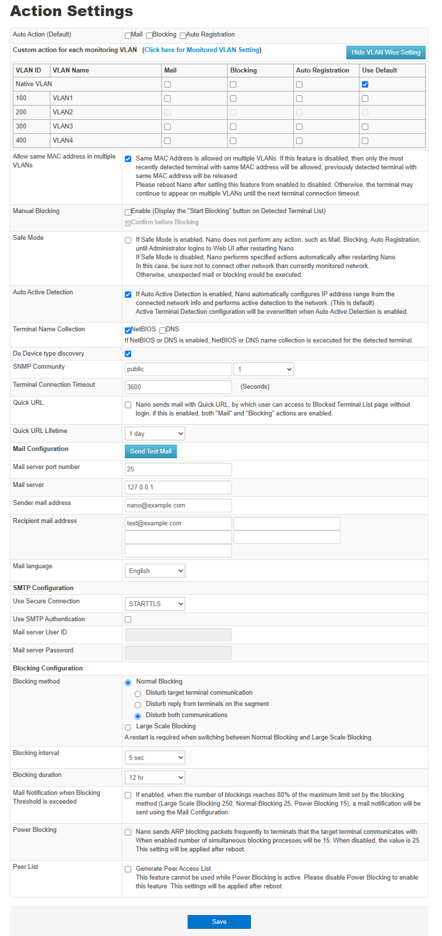
The Action Settings has the following items.
| Item | Description |
|---|---|
Configure the action to take when an unregistered terminal is detected. Either Blocking or Auto Registration and Mail notification can be selected. Default action for "Custom action for each monitoring VLAN". Auto Action is executed for the unregistered terminals that is detected after setting the action. |
|
Select the action for each VLAN. |
|
Allow same MAC address in multiple VLANs |
If this setting is enabled, terminal with the same MAC address on multiple VLANs will be displayed. If this setting is disabled, only the most recently detected terminal with the same MAC address will be displayed, and previously detected terminals with the same MAC address will be marked as terminated. If you change this setting from enabled to disabled, the terminals may continue to appear on multiple VLANs until it is shut down, so please restart Nano. This setting is for Nano(V) only. |
Manual Blocking |
Configure the manual blocking. If you check "Enable", "Start Blocking" button is displayed on Detected Terminal List. If you check "Confirm before Blocking", the confirm dialog is displayed then you click "Start Blocking". |
Check this to enable Safe Mode. Safe mode is a mode of operation in which actions will not be executed, unless you log in as the administrator after restarting Nano. By enabling this, you can mitigate accidents such as unintentional Blocking occurring when you move your Nano and accidentally connect it to a different network. Once you’ve stabilized your Nano’s location and settings, disable Safe Mode to execute configure actions without administrator intervention on every reboot. |
|
Check this to enable Auto Active Detection. (Default Configuration). When Auto Active Detection is enabled, Active Detection Settings are configured based on network information configured automatically or manually. For more information about the auto settings, see Active Detection.
|
|
Terminal Name Collection |
Select this to display the NetBIOS name or DNS name as the terminal name in Detected Terminals List. |
Do Device Type Discovery |
Select this to display the Device Type in Detected Terminal List. Nano will SNMP access to each terminals when discovering. |
SNMP Community |
Configure the SNMP community string to be used for SNMP access when discovering Device Type. |
SNMP Version |
Configure the SNMP version to be used for SNMP access when discovering Device Type. |
Terminal Connection Timeout |
It is the time after which the detected terminal will be released from its current state and return to the undetected state again. |
Quick login URL setting |
|
Quick URL |
If this setting is enabled, a URL that can be used to access the "Blocked Terminal List" without login operation will be generated and notified by Email. |
Quick URL Lifetime |
Configure the validity period of the Quick URL. |
Mail server port number |
The port number of the mail server used for Email notification. |
Mail server |
The IP address of the mail server used for Email notifications. When valid DNS server information is configured, it can be specified by FQDN. |
Sender mail address |
The Email address of the sender for Email notification. |
Recipient mail address |
The Email address to which Email notification is to be sent. Up to 5 can be registered. |
Mail Language |
Select the language for Email notification. You can choose between Japanese and English. |
Use Secure Connection |
Select the communication method with the mail server. |
Use SMTP Authentication |
Select whether to use mail server password authentication when sending mail. |
Mail server User ID |
The user id defined in the Mail server for password authentication. |
Mail server Password |
The password defined in the Mail server for password authentication. |
Blocking method |
Please select the Blocking method from Normal Blocking or Large Scale Blocking.
When using Normal Blocking, the number of terminals that can be blocked at the same time is 25 for both IPv4 and IPv6 addresses. (If "Power Blocking" is enabled, the number will be 15 for each.)
|
Blocking interval |
The interval at which blocking packets are sent. |
Blocking duration |
The duration for blocked. |
Mail Notification when Blocking Threshold is exceeded |
If this setting is enabled, when the number of blocking attempts reaches 80% of the upper limit set by the blocking method (Normal Blocking: 25, Power Blocking: 15, Large Scale Blocking: 250), an email notification will be sent based on the "Email Settings" setting . Once a threshold exceeded email has been sent, further email notifications will be suspended for one hour to avoid continuous email notifications. If a new blocking occurs one hour later and the threshold is exceeded, an email notification will be sent again. |
Power Blocking |
Can enhance blocking. If this setting is enabled, it will more powerfully block IPv4 communication from other terminals to the target terminal. Packets to prevent replies will always be sent to terminal that have confirmed communication with the target terminal. When this setting is enabled, the number of terminals that can be blocked at the same time is up to 15 terminals. (Up to 25 terminals when disabled) Default setting is disabled. This setting will be applied after reboot. |
Peer List |
You can generate a Peer List. When this setting is enabled, Nano records which terminals communicate with each other and when, displaying this information in a list within Nano Manager. For details on displaying the Peer List, refer to the Nano Manager User Manual. This feature cannot be used while "Power Blocking" is enabled. The default setting is Disabled. This setting will be applied after reboot. |
Related operations
Email Notification
Notify the specified Email address when an unregistered terminal is detected.
-
Open Action Settings
Click on "Nano Management" > "Action Settings" in the top menu.
-
Set Mail Configuration
Set the following items.
Item Description Auto Action (Default)
Set the action to take when an unregistered terminal is detected. Select Mail.
Mail server port number
Port number of the mail server used for Email notification. Enter an appropriate port number.
Mail server
The IP address of the mail server used for Email notification. Enter an appropriate IP address.
Sender mail address
The Email address of the sender for Email notification. Enter an appropriate Email address.
Recipient mail address
The Email address to which Email notification is to be sent. Enter the Email address which should receive the notification.
Use Secure Connection (optional)
Check if the mail server uses secure connection.
Use SMTP Authentication (optional)
Check to use password authentication when sending Email.
Mail server User ID (optional)
User name used for password authentication when sending Email. Enter an appropriate user name.
Mail server Password (optional)
Password used for password authentication when sending Email. Enter an appropriate password.
-
Save
Click on Save, at the bottom of the screen, to save the settings.
Specifications of Supported SMTP Servers
| Function | Specification | |
|---|---|---|
Authentication |
None |
|
Available (Auto Selection) |
PLAIN |
|
LOGIN |
||
CRAM-MD5 |
||
Encryption |
None |
|
SSL/TLS |
||
STARTTLS |
||
Example Settings for Outgoing Mail Server
Below are SMTP server configuration examples for major email services.
When Using Gmail’s SMTP Server
To use Gmail’s SMTP server, you need to obtain a Google account, enable two-factor authentication, and issue an app password.
Steps to Issue an App Password
The following steps are as of December 2024. Please refer to Google’s website for the latest detailed information.
-
Open the "Manage your Google Account" screen in a web browser
-
Select "Security" from the menu on the left
-
From the "How you sign in to Google" section, select "2-Step Verification"
-
If 2-step verification is not set, configure it here
-
-
Select "App Passwords"
-
Enter an app name (any string) and create the app password
Configuration Example
-
When using STARTTLS as the encryption method
Item |
Example Setting |
|
Mail Configuration |
Mail server port number |
587 |
Mail server |
smtp.gmail.com |
|
Sender mail address |
Your Gmail address |
|
SMTP Configuration |
Use Secure Connection |
STARTTLS |
Use SMTP Authentication |
ON |
|
Mail server User ID |
Your Gmail address |
|
Mail server Password |
Mail server Password |
|
-
When using SSL/TLS as the encryption method
| Item | Example Setting | |
|---|---|---|
Mail Configuration |
Mail server port number |
465 |
Mail server |
smtp.gmail.com |
|
Sender mail address |
Your Gmail address |
|
SMTP Configuration |
Use Secure Connection |
SSL/TLS |
Use SMTP Authentication |
ON |
|
Mail server User ID |
Your Gmail address |
|
Mail server Password |
Mail server Password |
|
When Using Yahoo! Mail SMTP Server
To use Yahoo! Mail’s SMTP server, you need to obtain a Yahoo! Japan ID, enable SMTP usage, and set a password.
Steps to Enable SMTP and Set Password
The following steps are as of December 2024. Please refer to Yahoo! Japan’s website for the latest information.
-
Open Yahoo! Mail in a web browser
-
Click the gear icon in the upper right and open the "Mail Settings" screen.
-
From the menu on the left, select "IMAP/POP/SMTP Access"
-
Select "Enable access from services other than official Yahoo! JAPAN"
-
Set either or both IMAP/POP and SMTP to "Enable"
-
-
Click the "Save" button
-
Open Yahoo! Account Management (Registration Information) screen
-
You can go there by clicking your account name in the upper left of the Yahoo! Mail screen
-
-
In the "Login and Security" tab, click "Set" under "Disable/Change Password"
-
Set a password using any string
Configuration Example
| Item | Example Setting | |
|---|---|---|
Mail Configuration |
Mail server port number |
465 |
Mail server |
smtp.mail.yahoo.co.jp |
|
Sender mail address |
Your Yahoo! Mail address |
|
SMTP Configuration |
Use Secure Connection |
SSL/TLS |
Use SMTP Authentication |
ON |
|
Mail server User ID |
Your Yahoo! Japan ID |
|
Mail server Password |
Configured Password |
|
Error Messages Displayed in Test Email Sending Feature
If sending a test mail fails, the result section below the "Send Test Email" button on the "Action Settings" screen will show the error message as follows:
Result: Error Content (Log Message (Configuration Details))
| Item | Description |
|---|---|
Error Content |
The mail sending process that encountered the error |
Log Message |
Message from the failed process |
Configuration Details |
Settings related to the failed process |
Below are example error messages and common causes. Note that messages and contents may vary depending on network and server settings.
-
Failed to Resolve Hostname
The "Configuration Details" will show the mail server name (FQDN) that DNS failed to resolve.
Result: Failed to resolve hostname (SMTP server name resolution failed (Configured server name))
This message appears when DNS name resolution fails. Please verify the server name setting.
-
Connection Failed
The "Configuration Details" will show the IP address, port number, and encryption method of the mail server. Please verify the settings.
Result: Connection failure(SMTP connection has failed(Mail server,Mail server port number,Use Secure Connection): Error: Net::SMTPS: connect: No route to host)
This message appears when the configured mail server’s IP address cannot be reached, or when the route to the mail server at that address cannot be verified.Verify mail server and the "default router" settings.
Result: Connection failure(SMTP connection has failed(Mail server,Mail server port number,Use Secure Connection): Error: Net::SMTPS: connect: Connection refused)
This message appears when the connection is explicitly refused. Verify server port and access permissions (e.g., firewall).
Result: Connection failure(SMTP connection has failed(Mail server,Mail server port number,Use Secure Connection): Error: SSL connect attempt failed with unknown errorerror:140770FC:SSL routines:SSL23_GET_SERVER_HELLO:unknown protocol)
This message appears when accessing mail server that is not supported to use SSL/TLS using SSL/TLS.
-
Connection Timed Out
The "Configuration Details" will show IP address, port, and encryption method. Please check the settings.
Result: Connection timed out (SMTP connection has failed (Mail server,Mail server port number,Use Secure Connection): Error: ALRM: Connection timeout)
This message appears when no response is received in time. Check the mail server, port, encryption setting, and access permissions (e.g., firewall).
-
SMTP Authentication Failed
"Configuration Details" will show the username that failed to authenticate. Check the settings.
Result: Authentication failure(Authentication failure(Mail server,***,): 535: Error: 5.7.0 authentication failed)
This message appears when username/password is incorrect or the authentication method is unsupported. Also may appear if encryption is required but not enabled. Check the Mail server User ID, Mail server Password and encryption settings.
Result: Authentication required(SMTP 'mail' command has failed: 530: Error: 5.7.0 Authentication Required)
This message appears when trying to send without authentication to a server that requires it. Check the SMTP configuration.
Result: Authentication failure(SMTP 'auth' command has failed (Mail server,***,): 5: No proper auth mechanism found: Server advertised='DIGEST-MD5' Client proposed='CRAM-MD5 LOGIN PLAIN')
This message appears when the server only supports methods not supported by Nano. Check the server’s supported methods.
Blocking
Block the terminals not on the ATL.
-
Open the Action Settings
Click on "Nano Management" > "Action Settings" in the top menu.
-
Blocking Configuration
Set the following items.
Item Description Auto Action (Default)
Set the operation to be done when an unregistered terminal is detected. Select Blocking.
Blocking interval
This is the interval at which the packets for Blocking are sent. Choose the required interval.
Blocking duration
This is the period during which blocking is done. Choose the required period.
Blocking method
It is way of blocking. There are 3 blocking methods, "Disturb target terminal communication","Disturb reply from terminals on the segment","Disturb both communications". Select the required method.
-
Save
Click on Save at the bottom of the Action Settings screen.
Auto Registration
Add detected terminal to ATL automatically.
-
Open Action Settings
Click on "Nano Management" > "Action Settings" in the top menu.
-
Set Auto Registration Configuration
Select Auto Registration from "Auto Action (Default)".
-
Save
Click on "Save" at the bottom of the screen to save the settings.
License Management
From this screen, you can register and delete the license code to activate the Nano extension module.
Related operations
Register License
Register License.
-
Open License Management
Click on Nano Management > License Management in the top menu.
-
Register License
Enter your license code and click the "Register" button. The license is registered if correct. The "Register" button is activated when the license is completely entered.
Delete License
Delete License.
-
Open License Management
Click on Nano Management > License Management in the top menu.
-
Delete License
Click on "Delete" button next to the license you want to delete and a confirmation dialog will be displayed. Click on "Delete" to delete. Click on "Cancel" if you do not want to delete.
Common screens
Header
The following items are displayed at the top of all screens except for the Login and Nano Setting/Network Setting screens.
The Menu-bar below the NetSkateKoban Nano banner provides access to the functions of NetSkateKoban Nano.
| The Menu-bar does not appear in the Login and Nano Setting/Network Setting screens. |
The menu items and corresponding functions are shown below.
NetSkateKoban Nano Functions
| Function | Sub-Function |
|---|---|
Terminal List |
|
ATL Setting |
|
Reports |
|
Nano Management |
Nano Setting/Network Setting |
Help |
Help for the current screen |
Logout |
Log out |
▲(▼) |
Click on ▲ to hide the NetSkateKoban Nano banner |
Footer
The following items are displayed at the bottom of all screens except for the Login and Nano Setting/Network Setting screens.
The contents and explanations are as follows:
NetSkateKoban Nano Footer items
| Position | Description | Comments |
|---|---|---|
Above the separator |
Status of Mail action |
|
Below the separator |
(1) Copyright notice |
Copyright notice |
About Linkage Products
Linkage Products Manuals
For information on Syslog messages and SNMP Traps corresponding to the linked Events refer to the documentation provided by the vendors.
Pointers to descriptions of some Events referred to in this package are provided below.
| # | _Event_ Name | Function / Use | Document Name | Reference Title information(Page) |
|---|---|---|---|---|
1 |
Website_Blocked |
Content Filtering Service |
SonicWall® SonicOS 6.5 Policies Administration |
Managing CFS Profile Objects (p.252) |
2 |
AV_Gateway_Alert |
Gateway Anti-Virus Protection |
SonicWall® SonicOS 6.5 Security Configuration Administration |
Enabling SonicWall GAV (p.167) |
3 |
IPS_Prevention_Alert |
Intrusion Prevention Service |
SonicWall® SonicOS 6.5 Security Configuration Administration |
Enabling IPS (p.167) |
4 |
IPS_Detection_Alert |
Intrusion Prevention Service |
SonicWall® SonicOS 6.5 Security Configuration Administration |
Enabling IPS (p.167) |
5 |
Botnet_Responder_Blocked |
BotNet |
SonicWall® SonicOS 6.5 Security Configuration Administration |
Configuring Botnet Filtering (p.230) |
6 |
fgTrapIpsSignature |
IPS |
FortiOS Log Message Reference 7.2.11 |
IPS (p.70) |
7 |
fgTrapIpsAnomaly |
Anomaly Detection |
FortiOS Log Message Reference 7.2.11 |
Anomary (p.71) |
8 |
fgTrapAvVirus |
Virus Detection |
FortiOS Log Message Reference 7.2.11 |
AntiVirus (p.68) |
9 |
fgWebFilter |
Web Filter |
FortiOS Log Message Reference 7.2.11 |
Webfilter (p.69) |
10 |
fgDNSFilter |
DNS Filter |
FortiOS Log Message Reference 7.2.11 |
DNS (p.73) |
11 |
fgIpsC&CBotnet |
BotNet |
FortiOS Log Message Reference 7.2.11 |
IPS (p.70) |
12 |
fgAvSandbox |
Sandbox related |
FortiOS Log Message Reference 7.2.11 |
AntiVirus (p.68) |
About product specifications
Hardware specifications
The hardware specifications of NetSkateKoban Nano are as follows. There is no difference depending on the model number.
| Item | Specifications |
|---|---|
External dimensions |
Approx. 24.3(H) x 83(W) x 58(D)mm |
Weight |
Body: Approx. 80g |
LAN interface |
100BASE-TX/10BASE-T x 1 port |
Power supply |
Attached AC adapter: AC100-240V, 50/60Hz, 2.0A, PSE compatible |
Power consumption |
Typical 1.2W |
Operating temperature range |
-20 to +70℃ |
Differences between model numbers
Each model has different performance and features, as given below, depending on the model number of NetSkateKoban Nano. Functions related to VLAN are exclusive to Nano(V).
| Product Name [Note1] | Model Number | Max Monitored Terminals | Max Allowed List | Max Monitored VLANs [Note2] |
|---|---|---|---|---|
NetSkateKoban Nano |
|
2048 |
20000 |
- |
NetSkateKoban Nano(V) |
|
2048 |
20000 |
10 |
NetSkateKoban Nano(V) |
|
2048 |
20000 |
40 |
|
Note1
NetSkateKoban Nano(V) is a NetSkateKoban Nano that supports networks configured with VLANs.
|
|
Note2
The maximum number of monitored VLANs includes the native VLAN.In the case of NSK-NANO-VB0AX, the number of native VLANs is 1 and the number of optional VLANs is 9, making a total of 10.In the case of NSK-NANO-VB4AX, the number of native VLANs is 1 and the number of optional VLANs is 39, making a total of 40.
|
| 'Nano(V)' in this Help refers to Nano with model number 'NSK-NANO-VB0AX' or 'NSK-NANO-VB4AX'. |
Supported browsers
We support the latest versions of Google Chrome, Microsoft Edge, and Mozilla Firefox.